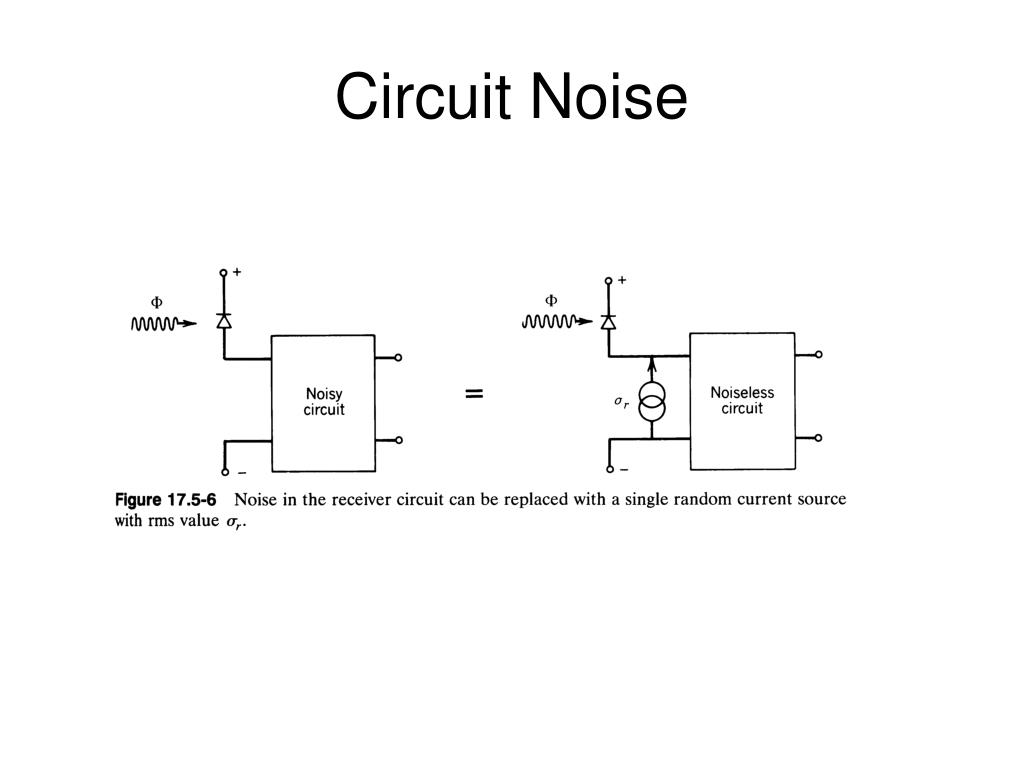
QUCS NOISE VOLTAGE SOURCE SERIES
The template computes all these with a series of intermediate waveforms using differential, integral, signum and other functions. The peak heights and peak sharpness for parallel (positive) and series (negative) resonances can also be obtained as Dirac-like pulses and summed up automatically with cumulative sum. The area under the relative impedance deviation is computed with definite integral calculus. Phase differential is intuitively related to the quality factor.

Then we can compute several further variables from that and from the impedance phase curve. (Another paper called them “scores.”) We can compute a fitted impedance curve as a moving average to cut between the peaks, then compute the deviation from it in relative terms. We can measure the flatness using several arbitrary metrics computed from the impedance profile, then combine them into a single number (FIGURE 9). Achieving flat impedance profiles (Q 0 total MLCC cap quantity equal to the number of power pins on the ASIC bulk cap quantity less than a user-defined maximum and a flatness metric limit to help with other goals indirectly. The whole impedance profile would need shifting down, not just the target impedance line. Adjusting the target impedance is not sufficient because cases can occur when an adjusted target impedance is already met by the original design’s impedance profile, but it still fails with RW noise amplitude that’s too large. The industry has been evaluating different approaches to dealing with RWs: for example, adjusting the target impedance or flattening the impedance profile. This is sometimes called rogue waves (RW). From recent research and publications, we know the target impedance method for analyzing PDN design does not always predict the worst-case noise voltage because different frequency components of the chip supply current load steps can superposition on top of each other. For power distribution networks (PDN digital chip supply rail), this is typically done by comparing their impedance profiles against a target impedance requirement. Here we present a new design/analysis method for estimating rogue wave amplitudes we can compare against the digital chip specs for design verification.Įlectrical designs must be verified against possible worst-case conditions. In recent years, additional considerations surfaced about rogue waves, but more as a general discussion. NTI 100: The Unsinkable, Unstoppable PCB MarketĮffective strategies for calculating rogue wave noise levels.įor about 20 years, PDN design and analysis focused on the target impedance method. Results of the annual PCD&F design engineer salary survey.Įnsuring proper alignment of layers and components on a PCB.

The ECAD Industry is Firing on All Cylinders.


 0 kommentar(er)
